


August 2022 Street Triple Project
I decided to get started on the project of adding brake pressure data to my 2018 Triumph Street Triple 765 RS since I've had the parts sitting on my workbench for a few weeks now. I have some ideas about doing some street riding videos demonstrating some of these concepts about using brakes at turn-in, holding brake pressure until you can take away lean angle and see the exit, etc. The Street Triple occasionally gets track duty so having the brake pressure data would be helpful for that too. If I ever decided to go all out and convert it to a track bike it would obviously be nice to have the sensor wired up ahead of time.
I already worked with Mitch Minton (out of Tennessee) to build a more comprehensive CAN profile for the Triumph 765 platform which includes TC engagement, riding modes and TC settings, hand throttle position and throttle body position, and front and rear wheel speeds. This adds to the existing CAN profile that AiM had for the 2013+ Daytona which appears to work for all the modern triples. That profile included RPM, gear position, throttle body position, 'vehicle' speed (which is derived from rear wheel speed), intake temp, coolant temp, and a couple of other minor channels. Once I've finished plumbing in the sensor and building the wiring harness, I'll work with Mitch again to build a modified profile to add the brake pressure data.
With this setup, the idea is to use the existing CAN data and feed it into the MCE18 and add the analog brake pressure sensor into the CAN signal, and feed it to the S2DL with the single 712 cable (same connector as before) which will provide me with more comprehensive data.
Probably the most challenging thing is the space to execute this project. Because it's my street bike, I have a fair number of auxiliary-powered devices already. This includes a power distribution/switching/fuse setup for my heated vest, power for a front-mounted USB port and the control module that sits under the seat, and a couple of other small things. Being a naked bike, this makes under-seat space pretty tight but I test fit the MCE18 along with the other devices and I think it will work out okay. I'd already relocated the evaporative canister which freed up a good amount of room so I think the power distribution system and the MCE18 will both fit okay.
I'll document the project as I go, this page being the repository in case someone else is interested in this project for a modern Triumph triple bike. In theory, this could be done with any bike that has a CAN bus. I'll also ask Mitch to provide a config so that I can later add a rear brake pressure sensor, particularly since this project is focusing on street riding where I actually use the rear brake in certain scenarios.
For whom would this project be useful?
My line of thought here is that I already had a Solo 2 DL and I have a very comprehensive set of measures from the bike's ECU via the CAN bus already. The glaring missing component though was brake pressure. As I've written before, it's possible to derive braking from effective longitudinal deceleration, but I wanted to capture brake lever pressure directly, and hence this project. If you're building a data logger system from scratch and haven't purchased hardware yet, an AiM MXm dash would be a simpler way to go. However, if you already have the S2DL or you don't have room for the dash or maybe you use the S2DL on multiple vehicles, this might make more sense, as it did for me. The biggest limiting factor of the S2DL natively is that it does not have analog inputs. Adding analog inputs to the unit as a standard offering would dramatically complicate the installation, it would render it mostly non-transferrable, and it would add considerable cost. As of 2022, the S2DL retails for $800 (assuming you can find one), the MXm dash is ~$1200.
In order to execute this project, with the end goal being to use an AiM Solo 2 DL (which does NOT have analog inputs), I'm using the following parts:
Bosch 0-2000psi pressure sensor and connector (from EFI hardware)
Assorted wire, including 18ga 3-conductor weatherproof (for the brake pressure sensor back to the MCE18) and various colors of single conductor to easily identify what's going where
AiM S2DL cable, unterminated on the opposite end with leads for CAN +/-, RPM, power, and ground; I ended up using the same AiM OBDII cable since, as it turns out, I needed to piggyback onto the existing CAN network
As of 5:00 PM August 28th, 2022, the new plumbing is complete, the cables are routed and some of them are patched in to power and appropriate terminals. I've got switched power and ground for the S2DL and MCE18 on the dedicated power distribution, I've tapped into the CAN +/- leads on the bike, just a few things left to connect. I've put things back together though not everything has final routing since I will have to open up the tail section again to finish plugging in a few terminals. Hopefully, Mitch is able to get back to me soon so I can start testing it and we can make further adjustments as necessary. Everything fit and I'm happy with the work I did. Invariably I had a small mess with brake fluid but I'm not sure when that doesn't happen on a full brake fluid flush, nothing too bad though. The bike is rideable, tools are cleaned and put away. Stay tuned for the final installation bits and testing.
August 29, 2022 Update
This evening I worked over the phone with Mitch since I'd plumbed the front brake and pulled and he did a remote session with my Windows laptop to adjust the custom Triumph ECU profile to accommodate the MCE18 which inserted CAN data for the analog brake pressure sensor.
I'm pretty new to actually understanding CAN data so a giant takeaway for me on this was that additional CAN devices piggyback onto the existing CAN bus. I was under the impression that the way things would work is that the MCE would effectively hijack the CAN signal coming from the bike before it went to the S2DL but in fact it connects in parallel, it's just another device feeding CAN data. This makes sense to me know as I think back on how it works in cars with all the various control modules (one for each door in my Audi, one for the reverse radar sensors, another for the camera, another for each power seat, etc. These all just tap into the CAN 'network' of the car with unique identifiers.
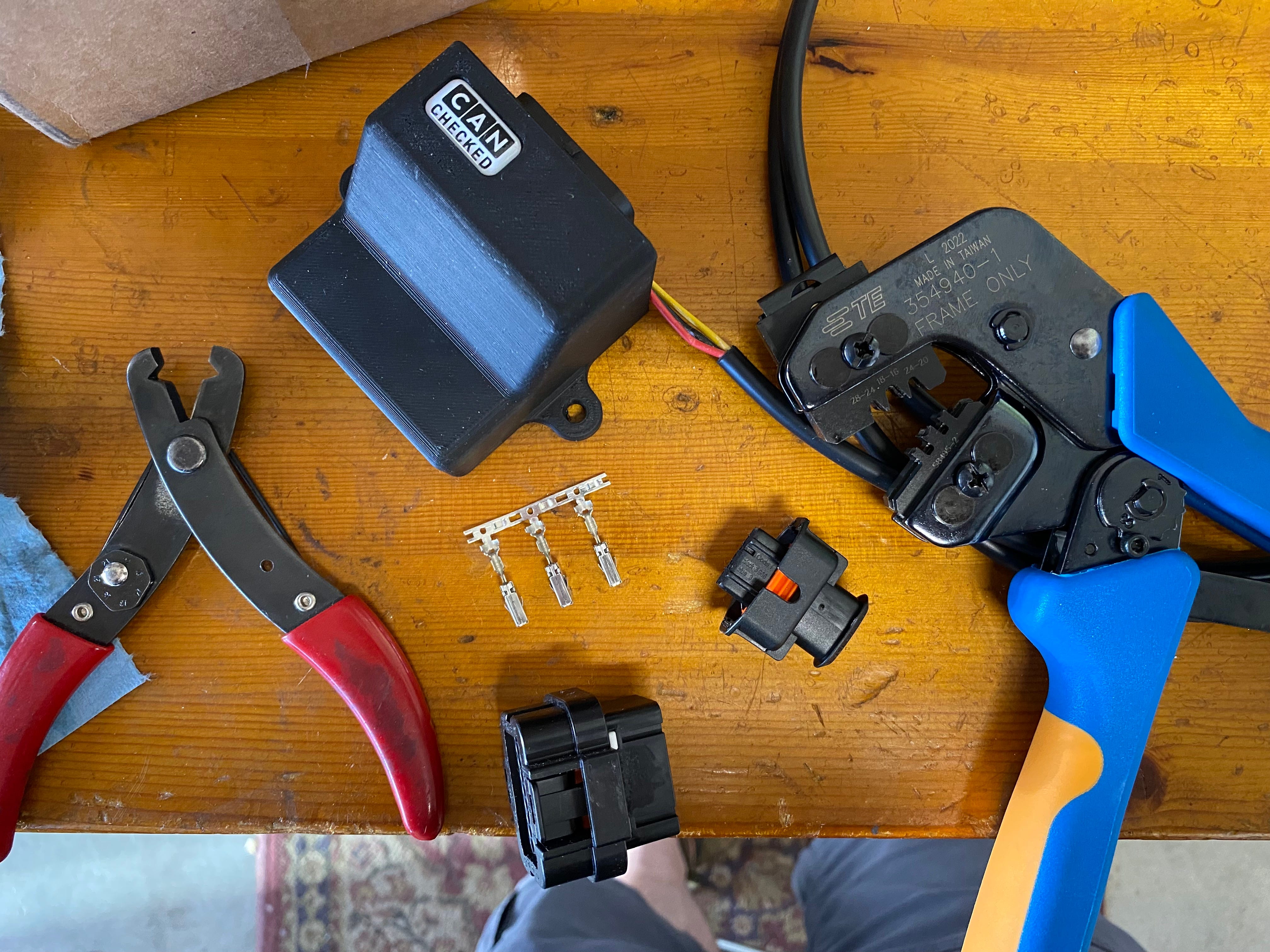
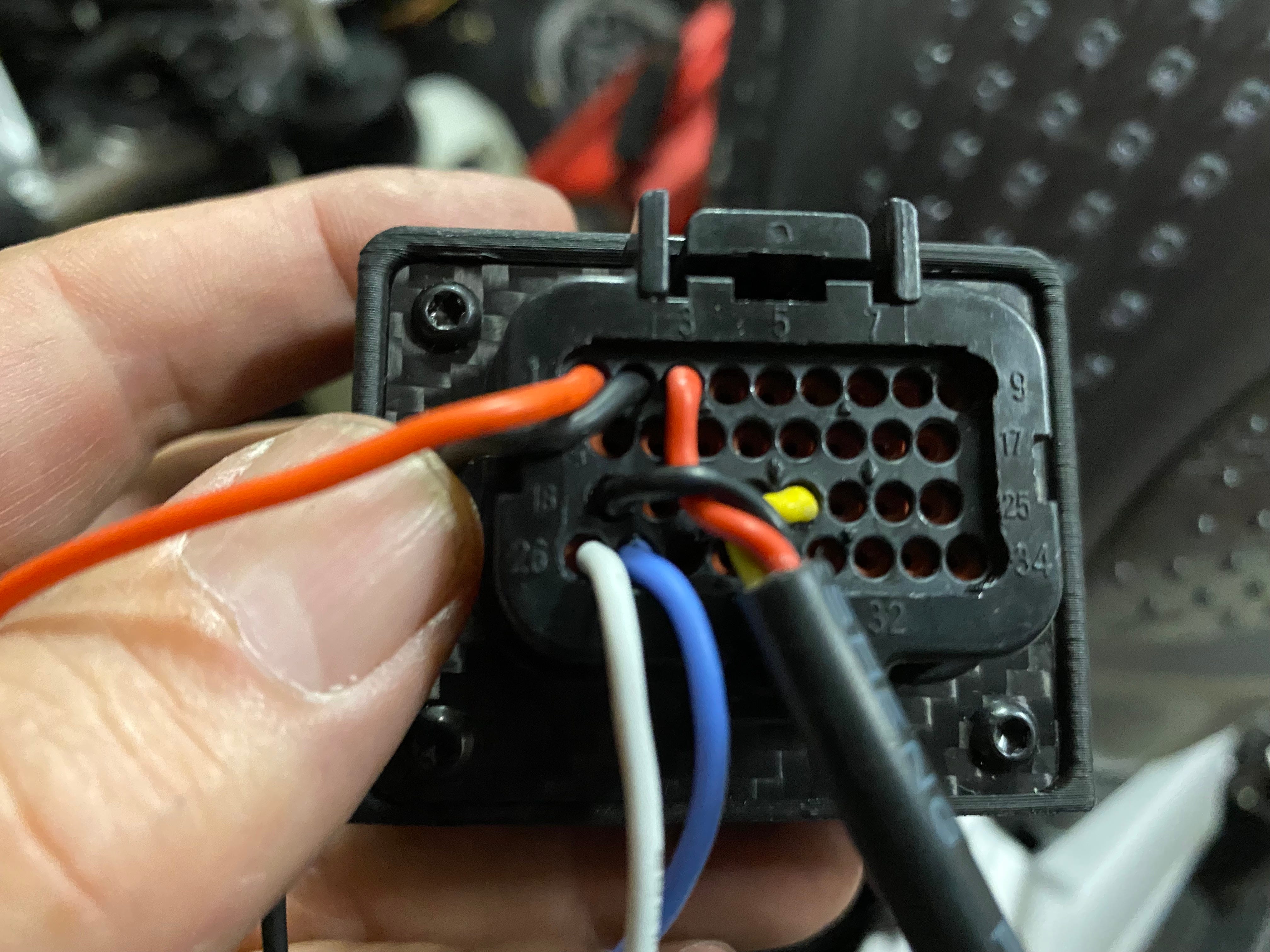
The CAN Checked MCE18 is a device that takes analog (and optionally digital) signal in and converts it to CAN signal. It has +5v outputs for going to things like suspension potentiometers, brake pressure sensors, etc. and then converts that to CAN signal which just piggybacks onto the CAN network (I installed Posi-tap connectors on the CAN + and CAN - wires in the diagnostics cables. Then with an additional protocol on the custom Triumph protocol Mitch had helped me with, he did the maths and wrote the channels for the MCE18 translating the 0-5v DC into code the S2DL can interpret and log.
So, now I'll share the details of my installation.
I already had an AiM Solo 2 DL (S2DL) connected to the bike via an OBDII cable (Triumph uses the OBDII connector for their diagnostics).
I had also added a ground pin to my S2DL installation on both of my Triumphs which allows the bike to charge the S2DL because it lacks the ground.
I added a relay to switch the ground with the ignition, this way if I leave the S2DL connected it doesn't drain the battery because the power is always on without switching the ground or the power. I don't like to 'molest' the bike's factory wiring so I will supplement or modify my own additions to prevent the need to alter anything stock. This makes it easier to troubleshoot should anything arise and when I sell the bikes it's easy for me to remove my additions to return it to stock.
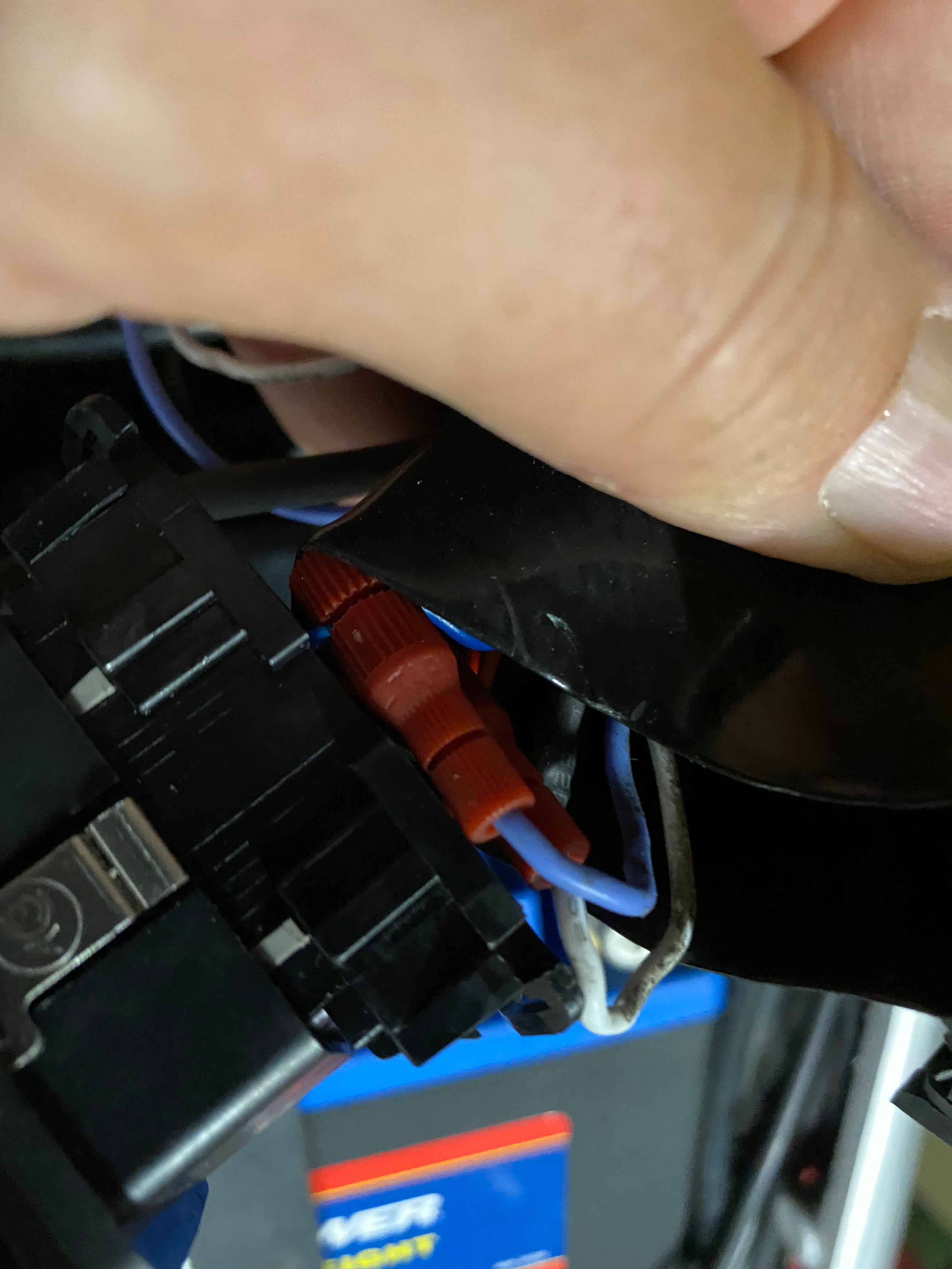
When I need to tap into the vehicle's existing circuits, I always try to do this in the least intrusive way. At present, my favorite electrical device is the Posi-tap connectors. They're a little expensive but they make it so easy to return to stock with minimal sheathing intrusion, they're reliable, and reusable.
I had already relocated the evaporative canister so that provided me room under the seat to add the power distribution (which was there for other reasons) as well as the MCE18. There's not a lot of space to start with so I'm not sure I could have added the MCE18 without relocating the evap canister.
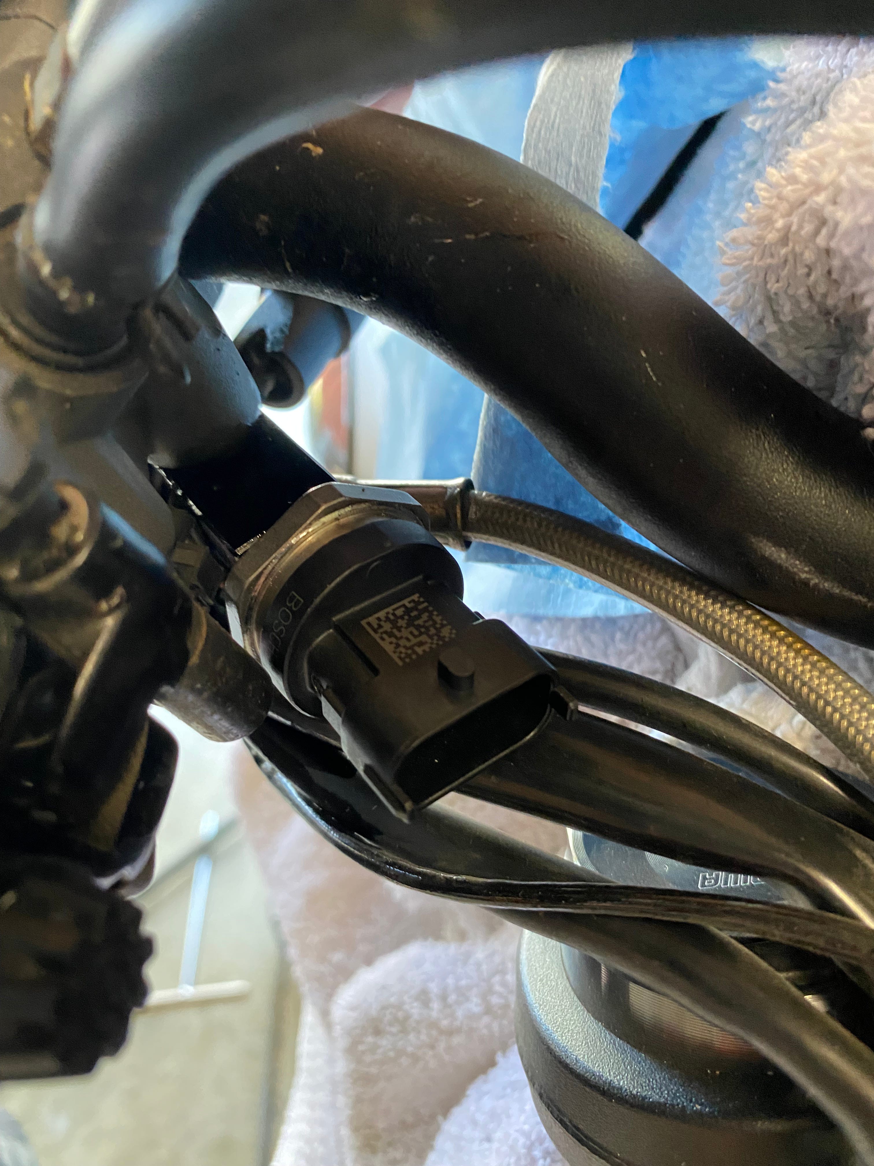
I added the brake pressure sensor (a Bosch 0-2000psi unit Mitch recommended (P/N: 0.261.545.053), though it was quite a bit larger than the AiM sensor but it didn't overly complicate the installation)
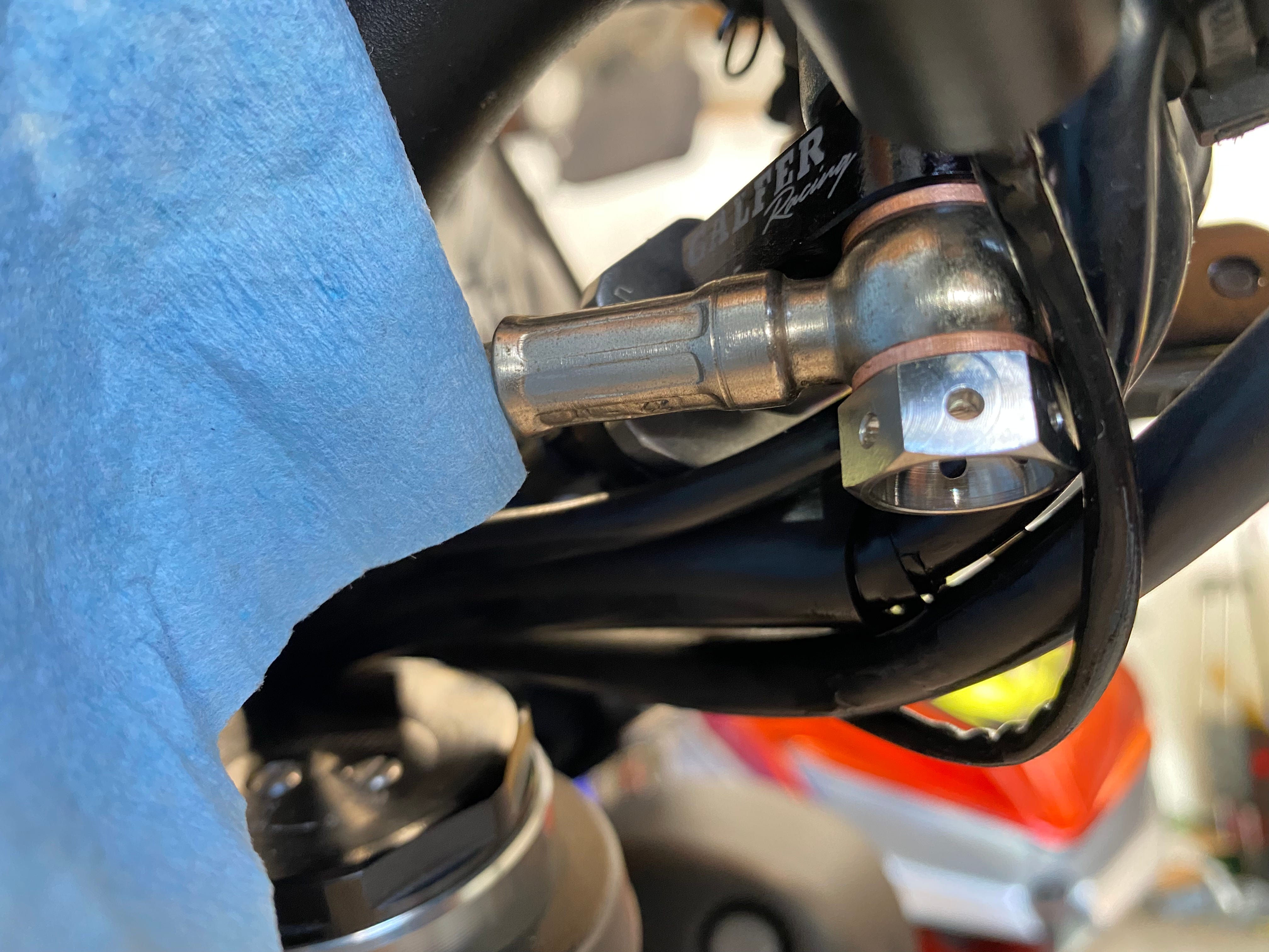
To connect the brake pressure sensor, you need to add it to the front brake line. I did this using the Galfer aluminum sensor block. You'll also need a double banjo bolt and new compression washers and of course, you'll have to do a full brake bleed once you've put it all back together.
I had to terminate the 3 wires that run between the brake pressure sensor and the MCE18 and run the cable from the front of the bike to the back. I used a 3 conductor weatherproof cable and ran it under the tank, following the contours of the bike's frame and stock harness. The terminations are done using a barrel crimp tool. I have a mid-grade one which was a lot more expensive than any other crimper I've owned but it works well and makes a nice crimp.
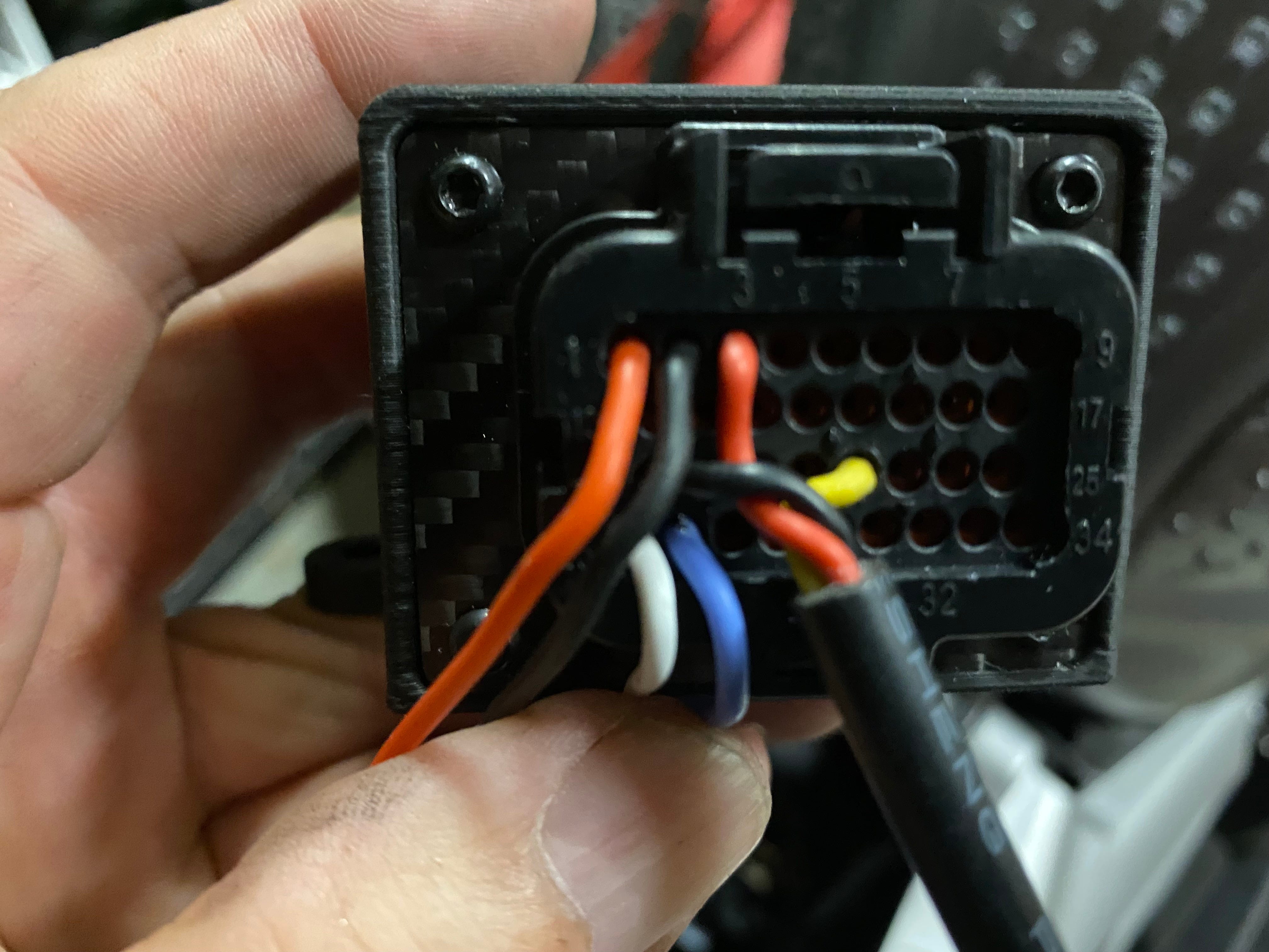
The MCE18 is connected to switched power and chassis ground (I did this using my power distribution module previously installed, but if you don't have that, I would have used the circuit for the license plate light since it's nearby). The 3 leads for the brake pressure sensor are connected directly to the MCE18 (+5v, ground, and signal). Then the MCE18 has a pair of connections that piggyback onto the bike's existing CAN leads (CAN +/- aka CAN High/Low).
Finally, I did a remote session via TeamViewer with Mitch and we worked through the maths and configured interpretation of the data from the signal coming from the MCE18 and how it is translated into the S2DL.
Then, button things up, test, and reported back to Mitch and then we did a few fine tuning adjustments to get the brake pressure zeroed out.
I updated my S2DL to add a display that includes some Triumph Measures, including brake pressure. This allows me a quick way to check the functioning of the brake pressure sensor as well as using that to give myself a way to feel how much brake pressure I'm applying to the lever (knowing that about 12-14 bar is my typical maximum.

Takeaway and how you can use this
If the S2DL is the most logical device for your situation and you want to capture more data from your bike than what's available in the stock AiM profile or if you work with Mitch Minton (or someone else) to extract more data (or if AiM doesn't already have an ECU profile for your vehicle) but you're still missing some data you hope to capture, this project might make sense. Though this project was done on a motorcycle, it is entirely possible for cars as well.
It does require a bit of logic, thinking through the process, and some adaptability. You are going to have to do some electrical work but in this case, because of the connectors I've chosen, I didn't even have to break out a soldering iron (not that I'm afraid to, but I just tapped into existing circuits and crimped connectors).
Expense wise, if you have to add an analog brake pressure sensor(s), figure ~$200 for the front and the same for the rear (if you want to use that too). The MCE18 was ~$225, cables were ~$40 and the barrel crimper from ProWireUSA was ~$200 (there are cheaper ones on Amazon, but I can't confirm how well they work).
Expanded Triumph Custom ECU Profile
MeasureAiM ProfileCustom ProfileRPMXXGearXXThrottle Body Position (degrees)XIntake Air TempXXCoolant TempXXVehicle Speed (rear wheel)XXBattery VoltageXXThrottle Body Position (%)XThrottle Hand Position (%)XTC ModeXThrottle MapXWheel Speed FrontXWheel Speed RearXTC Activation/EngagementX
The custom profile adds several measures and also important, especially when comparing your own data to riders on other bikes, is the more standardized throttle position as a percentage instead of being measured in degrees. Also very important is that the new profile includes throttle hand position, which is of course only available on bikes with throttle-by-wire. Since I run in Track mode, there is a 1-to-1 throttle hand to body relationship but all the same, I can control what my hand does, not what the bike's electronics do. I like having TC Engagement because if I'm not triggering it on exits, I know I can use more throttle sooner. So far I'm mostly just seeing it trigger while the bike is up and down which means wheelie abatement. I was hoping to be able to capture ABS engagement as well but that doesn't appear to be in the data stream. We still have ~12 or more unidentified channels in the stream so maybe if there's a lap I notice it activating I can make a note and review the unknown channels to see if that's it.
Hi Welly,
I got help with my custom AiM ECU profile from Minton Performance. It was a paid commission project and Mitch can be contacted via his website: https://mintonperformance.com.
Hi are you able to provide a link to download the aim profile with the expanded can data?